一、 Summary
1.1 Overview of power battery test system
The power battery test system is a network architecture composed of AC-DC, DC-DC power conversion, loop and data acquisition and processing real-time computer control system. The DC-DC module hardware (test circuit and data acquisition) is connected through the network adapter and host computer; each between hardware can be connected via LAN or Internet; PC operating system of each module of DC-DC devices can share a uniform standard, realize the power battery production line testing. The DC bus common battery pack charging and discharging test system not only improves the testing efficiency, but also reduces the cost of the product.
1.2 Scope of application
Customer needs:
The application range of battery pack capacity: 20-50kWh;
The application range of battery package voltage: 80-450VDC;
The peak current of the battery pack: 300A;
Limit discharge current of battery pack: 375A (30s)
According to our professional experience, the main equipment of the design is as follows:
|
序号
|
设备名称
|
型号
|
数量(套)
|
技术参数与说明
|
|
1
|
动力电池测试系统
|
WLD-300-550
|
1
|
高压直流母线电压:550Vdc;
双向DCDC额定电流:300Adc;
双向DCDC超载电流:375Adc;
|
|
2
|
上位机管理系统
|
WLD-Solution
|
1
|
动力电池测试管理软件/PC硬件
|
1.3软件系统结构
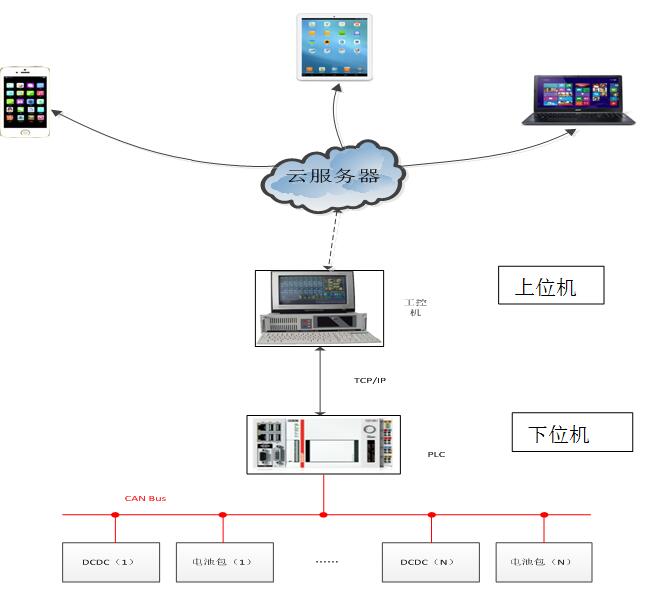
上位机软件由十几个软件模块组成,全部集成在一套上位机操作管理软件中。下位机DPS位于设备内部,将上位机指令下发给测试设备实现各种操作,同时将测试数据回传给上位机数据库。上位机软件Server与client高度一体化集成,保证测试系统长期稳定运行。同时上位机软件具有细分化的操作和功能权限,适用于不同使用者的需要。Server以TCP/IP方式与下位机通讯。
The lower machine DPS to achieve real-time monitoring of DCDC and battery pack, PC to achieve human-computer interaction, instruction upload down, local database, state identification and judgment function; cloud server is used for charging and discharging management decision and battery automatic test process modeling, remote monitoring
1.4 Extensibility of the system
Considering the future expansion requirements of users for power battery testing, the system provided by this plan has better flexibility for the expansion of test system (besides rated current / voltage / power), which is convenient for users to expand and adjust the system in the future.
For example, the production system has extensible characteristics.
The host computer software management system has a reserved interface to manage multiple test equipment.
1.5 Test standard for power battery
|
1.5.1
|
国际标准
|
|
|
国际标准化组织标准(ISO)
|
|
|
国际电工委员会标准(IEC)
|
|
|
美国汽车工程师学会标准(SAE)
|
|
|
日本电动车辆学会标准(JEVA)
|
|
|
欧洲标准化技术委员会(CEN)
|
|
1.5.2
|
国际标准协会
|
|
|
USABC(美国先进电池联合会)
|
|
|
FreedomCar(自愿合作的汽车研究计划2002~长期计划)
|
|
|
PNGV(新一代汽车合作伙伴计划19942004)
|
|
1.5.3
|
满足2015年4月颁布的新国标
|
|
|
QC/T 741-2014车用超级电容器
|
|
|
GB/T 31467.1-2015电动汽车用锂离子动力蓄电池包和系统第1部分:高功率应用测试规程
|
|
|
GB/T 31467.2-2015电动汽车用锂离子动力蓄电池包和系统第2部分:高能量应用测试规程
|
|
|
GB/T 31467.3-2015电动汽车用锂离子动力蓄电池包和系统第3部分:安全性要求及测试方法
|
二、Introduction of technical parameters
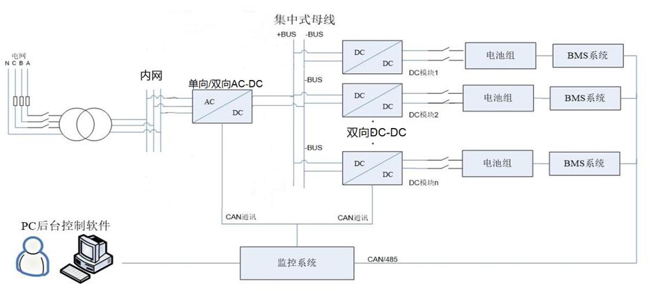
2.1 Electrical circuit diagram
2.2 Power battery test module: WLD- bi-directional DC-DC technical parameters
|
序号
|
类目
|
详细类目
|
参数
|
|
1
|
DC电压
|
高压侧DC电压(V)
|
100-800VDC (可设置)
|
|
|
|
低压侧DC电压(V)
|
80VDC-输入侧直流电压 (可设置)
|
|
2
|
DC电流
|
高压端DC电流(A)
|
(0-350)A (可超载375A≥60s)
|
|
|
|
低压端DC电流(A)
|
(0-350)A (可超载375A≥60s)
|
|
3
|
额定功率
|
输出功率(输出电压350V)
|
额定60KW持续,最大80KW不持续
|
|
4
|
转换效率
|
输入500V,输出300V
|
≥95%(在测试条件下取得)
|
|
5
|
最高变比
|
高压电压:低压电压
|
10:1
|
|
6
|
通道电压稳定精度
|
动态
|
2% (≤满量程的±0.1%FSR(0~40)℃)
|
|
|
|
静态
|
1%(≤满量程的±0.1%FSR(0~40)℃)
|
|
7
|
通道电流稳定精度
|
动态
|
5%(≤满量程的±0.1%FSR(0~40)℃)
|
|
|
|
静态
|
1%(≤满量程的±0.1%FSR(0~40)℃)
|
|
8
|
工作模式
|
设备具有斜坡充放电、恒压充放电、恒流充放电、恒功率充放电、恒负载放电功能;SOC标定;具有电池内阻测量功能(按照国标配置)
|
|
9
|
保护
|
过压、欠压、过流、过热
|
|
10
|
方向转换
|
双向DCDC接受RS485或CAN指令在线转换充电、放电状态
|
|
11
|
通信接口
|
RS485,全隔离
|
Modbus,RTU协议
|
|
|
|
CAN2.0A/B,全隔离
|
最高1M/S
|
|
12
|
通信功能
|
通过通讯功能能够控制系统的启动、停止、工作模式、电压、电流值等的设定
|
|
13
|
数据采集间隔
|
10ms
|
|
14
|
可持续的数据采集间隔
|
999HRS:59M:59.99S
|
|
15
|
程序步数
|
≤9999
|
|
16
|
程序步数设置时间
|
999HRS:59M:59.99S
|
|
17
|
程序循环次数
|
≤99999
|
|
18
|
动态响应能力(电池负载,电流无超调,可接受电压为限制条件)
|
0到充电或放电(100%满量程设定):≤20ms
充电到放电(100%满量程设定):≤40ms
放电到充电(100%满量程设定):≤40ms
|
|
19
|
安时数
|
* 9999.9
|
|
20
|
瓦时数
|
* 99999
|
|
21
|
能量回收
|
能量在DC母线均衡循环使用,避免电网污染及逆变损耗
|
|
22
|
外部CAN通讯
|
外部CAN变量参与系统工作控制,含CAN卡及标配CAN通讯线1根,接受.dbc文件导入,接受客户手动添加CAN变量,所有接收CAN变量可以作为限定条件并存储到上位机软件中,上位机软件系统变量可以传送给客户端;
|
|
23
|
绝缘电阻
|
输入—机壳≥200MΩ/500VDC
|
|
24
|
抗电强度
|
输入—机壳≤20mA 1.5kVDC/1min
|
|
25
|
接地导通电阻
|
外壳与安全接地线之间≤0.1Ω/10A
|
|
26
|
尺寸
|
WLD-DC200A:390*360*270(mm)(长*宽*高)
|
|
|
|
WLD-DC350A:390*540*270(mm)(长*宽*高)
|
|
27
|
重量
|
WLD-DC200A:30KG
|
|
|
|
WLD-DC350A:50KG
|
三、Software system function introduction
3.1 The working principle of power battery charging and discharging module DC-DC
1) DC-DC can be set up to charge and discharge mode by the command to the lower computer control DC-DC module through the host computer communication bus.
2) PC setting mode, DC-DC from the DC bus to take power according to the set mode, charge and discharge of the battery for charging the battery, first of all, the value of the constant current to charge the battery, the end stage of constant current can be set automatically into the constant voltage charging stage, constant pressure value should be set in advance, the battery is full automatic the end, a complete process of charging
3) discharge mode will power back to the DC bus, then back to the DC bus can be immediately for the other one is charging the battery pack provides power, DC bus voltage is higher than the set value of safety after going through resistance consumed, rather than return to the corporate intranet, avoid the pollution of power; if DC bus electric power shortage, DC bus through AC-DC power grid, power battery production line to batch testing of a dynamic equilibrium in the process of DC bus.
4) each channel DC-DC module can independently enable it or not.
3.2 Introduction of test system
Test management software is an integral part of the test system, it can be operated with the system software of the host computer in Windows XP or Windows 7 professional environment, service integration analysis process, implementation process, data collection and test results; user friendly, integrated design, user-friendly software; the design of architecture mature, with good scalability, easy to upgrade and maintenance.
3.3 Test system function
1) upper computer software
A) real time fault detection and processing
B) field bus control and data acquisition
C) light control
D) program writing, data record
E) battery capacity test
F) battery internal resistance test
G) battery standard dynamic test
H) constant current charge discharge, constant voltage charge discharge, constant power charge discharge, constant load discharge
I) SOP simulation test;
J) SOC simulation test;
K) SOH simulation test;
L) battery failure management;
2) FaceView software
A) human-computer interaction
B) database function and data display
C) PACK parameters and state recognition
D) communication with MES system
E) local database
F) charge and discharge strategy control, based on the shortest path design target, set the charge and discharge conditions of the battery package, and use the Dijkstra algorithm to obtain the optimal solution.
G) automatic battery testing process modeling
H) cloud database function
> restrictive conditions
> Time, current, voltage, power, temperature, cell assembly voltage
> input and zero of digital signal value
> ah / wh (cumulative value, charge and discharge cycles) external and internal circulation
3.5 data acquisition
The collected data are stored in the caching area of the lower computer and have the function of intermittent test. Even if the burst power is broken down, the integrity and consistency of the test can be maintained. Data acquisition is synchronized with program execution. The collected data can be output to EXCEL format file, and it can be queried according to certain conditions, such as time, data name and so on, so as to support batch data transfer function.
四、Test system upgrade scheme
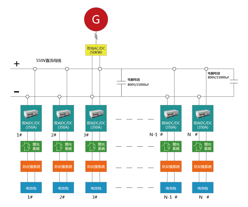
In accordance with the safety requirements, the anti reverse function can be installed. In order to make the battery pack more friendly, the pre charging system is attached. The system diagram is as follows:
Figure 2: diagram of battery pack test system with anti - back function
The installation of anti reverse function, when the battery pack is pushed into the test system, the test system can detect the battery pack voltage polarity is correct, if the reverse, the system will alarm signal, positive and negative access right after the first pre charge test system, the pre charge after the completion of DC relay will access DCDC low voltage battery pack.