A. Chinese elevator system
At present, the domestic elevator is generally a synchronous motor or an asynchronous motor with frequency conversion, and the structure is as follows:
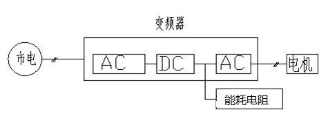
The energy consumption resistance is also called the brake resistance, and the regenerative energy of the motor is usually consumed by the brake resistance. The brake resistance generates a large amount of heat source, which causes the temperature of the elevator room to rise.
2. The energy-saving principle
1. Energy savings.
Energy is conserved, so energy conservation must have a source. The characteristics of elevator work are as follows:
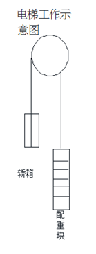
In general, the weight ratio of elevator in China is 40% to 50%, and the elevator is in operation. The weight of the car and the weight of the weight is different, so that the car and the weight block will generate the difference of gravitational potential energy in the process of fluctuation. The difference in potential energy needs to be provided either by the grid or by regenerative power to the dc end of the converter, which is consumed by the brake resistance.
Therefore, the source of energy saving in elevators is potential energy. When the potential energy needs to be overcome, the power grid will drive the motor through the inverter. When the potential energy is doing work, the potential energy is generated from the motor to generate electricity, which is fed back to the dc end of the converter.
The common practice of domestic elevators is that the energy generated from renewable electricity is consumed by braking resistance and energy is obtained from the grid when electricity is needed, thus wasting a lot of energy generated from renewable power generation.
2. Our plan.
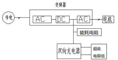
Internal structure diagram of energy saving device:
We design a system, the energy feedback process rapid recovery, and then rapidly release energy in the energy consumption process, thus saving a considerable energy, also is our plant the principle of energy conservation. Because the energy consumption process and energy feedback process can be short, it must be a quick recovery and release system.
Due to the above considerations, our system is directly connected to the dc bus of the inverter, and the supercapacitor is used as the energy storage system. In the process of energy feedback, the super capacitor can be charged quickly so that the energy can be recovered and the voltage of the converter dc bus is not increased. In the process of energy consumption, super capacitors are discharged rapidly and the power is injected into the dc bus of the converter, thus reducing the energy source of the city electricity.
3. Summary
We store the energy we consume and use it, which is the source of energy conservation.
The principle and theory of energy conservation are clear.
3. Power outage seamless switch energy saving program.
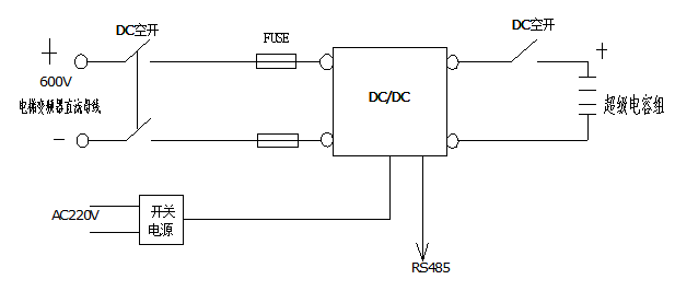
1. Internal structure of the energy saver.

2. Resource allocation
Reserve 2 optical coupling input signals for backup;
Reserve 2 channel optical coupling output signal backup;
Reserve 2 relay dry contact signal;
Reserve RS485 or CAN communication bus for standby.
The reserved resources are provided for the credit between the energy saving device and the electric control cabinet, such as emergency use, charging, discharge control, etc.
3. Connection with elevator system.

The part below the energy consumption resistance is the additional energy saving device. The high voltage of the energy economizer is connected to the positive electrode of the elevator converter dc bus, and the high voltage end of the energy saving device is connected to the dc bus negative terminal of the elevator converter.
4. Change of power supply of elevator control cabinet.
Power supply schematic of the original control cabinet:

110vdc: 2A ; 24v:1A
Power supply schematic diagram of the control cabinet after change:

After the change, the power supply of the electric control cabinet is charged from the dc bus of the converter.
Four. Bidirectional DC/DC technical parameters.
|
NO.
|
Electrical category
|
Detailed categories
|
specifications
|
|
1
|
Dc voltage
|
Input side dc voltage (V)
|
400-800Vdc
|
|
Output side dc voltage (V)
|
0—400 Vdc
|
|
2
|
Dc current
|
High voltage end dc current (A)
|
No more than 80A, 120A@100ms.
|
|
Low voltage dc current (A)
|
No more than 80A, 120A@100ms.
|
|
3
|
Conversion efficiency
|
Input 600V, output 300V.
|
95%
|
|
4
|
The highest variable than
|
High voltage: low voltage.
|
10:1
|
|
5
|
Rated power
|
Super capacitor output power.
|
Maximum power 12KW.
|
|
6
|
High voltage stability accuracy.
|
Super capacitor voltage boost state.
|
≤ ±1%
|
|
7
|
Communication interface
|
RS485, total isolation.
|
Modbus,RTU协议
|
|
CAN2.0A/B, complete isolation.
|
Top 1 m/S
|
|
8
|
display
|
无
|
|
12
|
size
|
390*180*270(mm)(length * width * height)
|
|
13
|
The weight of the
|
13KG
|
Five. Job description
1. When the elevator is in standby, the energy-saving device works.
The energy saving device increases the voltage of the supercapacitor voltage to maintain the voltage of the inverter at 600Vdc until the supercapacitor voltage is under voltage. The full power of the electric control cabinet is provided by the energy saving device to achieve the purpose of releasing the super capacitor energy as soon as possible, thereby reducing the energy demand for supercapacitors.
2. Working status of the energy saver when the elevator is braking.
Elevator braking, inverter dc bus voltage will rise, the author will quickly absorb the traction machine of renewable power generation energy, stored in the super capacitor, economizer of super capacitor current execute strictly limit flow, such as 80 a, the charging current is strictly less than or equal to 80 a.
If the energy saver can fully absorb the regenerative energy, the energy saving device will maintain the dc bus voltage of the inverter at 620Vdc. If it cannot be fully absorbed, the voltage of the converter dc bus will continue to rise to the energy consumption resistance to open the voltage threshold, and the excess energy will be consumed by the resistance.
3. Energy saving device working state of elevator.
When the elevator USES electricity, the energy economizer discharges the dc busbar of the converter, but strictly limits the discharge of ultracapacitors.
Current, not more than 80A.
If the elevator power is less than the energy saving device, the energy saving device provides all the power, and the voltage of the converter dc bus is maintained at 600Vdc. If the power of the elevator is greater than that of the energy saving device, the energy saving device provides some power, and the voltage of the dc bus is determined by the power grid voltage.
4. The energy economizer works when the electricity is suddenly cut off.
Elevator standby:
The energy saver gives full power to the elevator and tells the elevator that the electricity has been lost. The elevator will stop calling the request and open the door to wait for the power supply to stop. The elevator operates in a braking state: the economizer continues to recycle.
Energy, and tell the elevator that the electricity has been lost, the elevator will stop calling request, slow down to the nearest target station, open the door and wait for the power supply stop;
The elevator is running and utilization status, economizer to provide inverter dc bus 50 ms time full power, the inverter dc bus voltage drops to 500 VDC, and told the elevator mains have lost electricity, elevator
Should immediately slow down and anchor to the nearest floor, stop calling request, open the door and wait for the power supply stop;
No matter the state of the power failure, passengers do not have a sharp sense of pause, not immediately feel the fear of power failure, the elevator will gradually decelerate to stop, improve the user experience.
Six. Energy saving capacity allocation
The principle diagram of energy saving system is as follows:

The core components of the energy saving system are bidirectional DC/DC and supercapacitor energy storage system. The configuration and optimization of energy saving system are the collocation of these two core parts.
1. The DC/DC configuration
In this case, the bidirectional DC/DC of 80A is selected.
2. Super capacitor configuration.
In this case, the 48V/166F supercapacitor module 3 group was selected, and the charge and discharge range was 70-140vdc. Storage capacity is 400KJ, about 0.11kwh.
3. Size and weight.
Size: 450*300*1100mm (length * width * height)
Weight: 70KG.